Projekt LoRaWANDamit will ich mich auch mal beschäftigen. LoRa WAN (Long Range WAN).
Arduino Tutorials für Einsteiger
- Arduino Videokurs für den perfekten Einstieg – Arduino Tutorial (starthardware.org)
- https://www.arduinoforum.de/arduino_referenz_down.php
- Arduino-Referenz - Arduino-Referenz
- Befehlsübersicht.pdf (rwth-aachen.de)
- Hikro | Arduino Befehle - Liste mit Erklärung auf Deutsch
- Arduino-Einstieg: Schritt für Schritt mit Fotos und Erklärungen | Tutonaut.de
- Arduino Tutorial - Der Einstieg | EXP Tech (exp-tech.de)
- Arduino – Alles was du brauchst: Projekte, Tutorials, Code (starthardware.org)
- Arduino-Tutorial: Die allerersten Schritte (heise.de)
- Arduino Anleitung für Anfänger und Fortgeschrittene | Funduino - Kits und Anleitungen für Arduino
- index.php (hems.de)
- Arduino Programmierhandbuch (ov-meschede.de)
- Arduino Anleitung für Anfänger und Fortgeschrittene | Funduino - Kits und Anleitungen für Arduino
- Arduino Programmierung Archive - Technik Blog (draeger-it.blog)
LoRaWAN Tutorials für Einsteiger
- Mitmachklima: LoRaWAN als offenes Netz zur Daseinsvorsorge (umwelt-campus.de)
- Endlich verständlich: LoRa (und LoRaWAN) einfach erklärt! - LineMetrics Smart Building Plattform
- Was ist LoRa und LoRaWAN? Vorteile, Nachteile, Hintergründe. (lora-wan.de)
- lora-projektseminar.pdf (htw-dresden.de)
- LoRaWAN – Einen Sensor aktivieren (rs-online.com)
- Erstes Gerät im The Things Stack V3 — hhblog documentation (hs-augsburg.de)
Hilfreiche Links, Tools und Anbieter (Auswahl)
- Fritzing
- Lorawan Gateway u. Sensoren kaufen @ iot-shop
- LoRa Sensors | m2mGermany
- LoRa Sensoren | LoRa | IoT (LoRa, NB-IoT, RFID, M2M & Co) | ALLNET Fachhandel
- tekmodul GmbH
- LoRaWAN | RS Components (rs-online.com)
- LoRa (antratek.de)
- LoRa / LoRaWAN Gateway (dragino.com)
- LoRa - RobotShop
- OTAA und ABP - Die LoRaWAN Join-Verfahren (iot-shop.de)
- Was macht ein LoRaWAN Gateway? (iot-shop.de)
LoRaWAN steht für Long Range Wide Area Network und bedeutet bzw. ermöglicht ein energieeffizientes Senden von Daten über lange Strecken. Dies wurde speziell für das Internet of things (IoT) und Industrial Internet of Things (IIoT) entwickelt. Mit LoRaWAN ist es möglich mehrere hundert Sensoren innerhalb eines Netzwerkes zu verwalten und Sensordaten zu verarbeiten. Sensoren können bis zu 10 Jahren ohne Batteriewechsel betrieben werden.
LoRaWAN definiert das Standard Kommunikationsprotokoll und die Systemarchitektur für das Netzwerk, während LoRa die physikalische Schicht beschreibt, welche die „long range“ Kommunikationsverbindung ermöglicht. Die übergeordnete Organisation für LoRaWAN ist die LoRa Alliance.
Die LoRa Alliance ist ein offenes, gemeinnützige Organisation mit dem Ziel, das Marktbewusstsein für LoRaWAN als Übertragungsstandard zu fördern, Geräte zu zertifizieren und den weltweiten Einsatz von LoRaWAN zu unterstützen (Homepage - LoRa Alliance® (lora-alliance.org)
DARC LoRaWAN Hamgroup
Der DARC biete dazu eine HAM Group an (HamGroup LoRaWAN (p37.de). Die HAMGroup arbeitet mit dem LILYGO® TTGO ESP32 V2.1_1.6 868 MHz (LILYGO®TTGO ESP32 Paxcounter LoRa32 V 2,1 1.6.1 Version 433/868/915MHZ LoRa ESP 32 OLED 0,96 Inch SD Karte bluetooth WIFI Modul|Circuits| - AliExpress).
HAMgroup
- HAMgroups - DARC
- HamGroup LoRaWAN (p37.de)
- LoRaWAN-Workshop (p37.de)
- GitHub - DO6FP/hamgroup_lorawan: Repo containing examples and more used in the hamgroup LoRaWAN.
Was ist und was kann LoRaWAN?
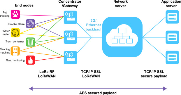
Dabei sieht die Struktur der LoRaWAN Netze immer wie folgt aus.
Ganz links auf dem Bild sehen wir Sensoren, die mit dem Gateway per Funk (EU 863 - 870 MHz) verbunden sind. Die Gateways sind via Internet oder 4 -5 G mit dem Network Server verbunden. Den Network Server kann man auch selbst betreiben, ansonsten stehen einige Cloudlösungen zur Verfügung. Die von den Sensoren kommenden Daten können dann auf einem Application Server für verschiedene Anwendungen zur Verfügung gestellt werden.
Ich habe den Cloudserver von TTN (The Things Network) ausgewählt, um erst einmal Erfahrungen zu sammeln (The Things Network).
Hierzu betreibe ich ein Femto Gateway Typ WLRGFM-100-EU868 (Indoor Femto LoRaWAN Gateway, WLRGFM-100-EU868 - Antratek Electronics)
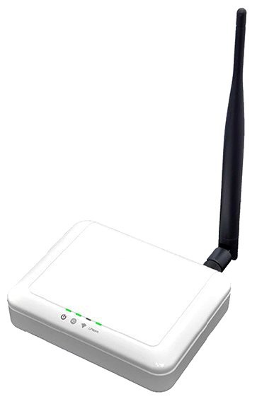
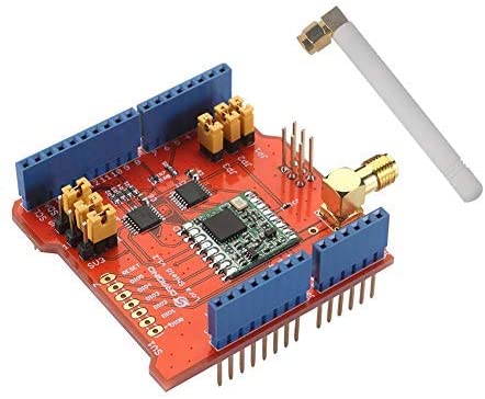
Diese Gateway muss mit der TTN Cloud verbunden werden. Den Node werde ich mit einem Arduino LoRaWAN Shield abbilden. Beim Kauf darauf achten, dass es sich um eine 868 MHz Version handelt.
Projekt 1
- Registrieren am TTN und Anmelden des Gateways
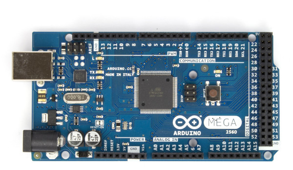
- Aufbau des Node, bestehend aus einem Arduino MEGA (Arduino UNO geht auch) und dem Dragino LoRaWAN Shield
- Verwendung eines DHT11 Sensor (Temperatur und Luftfeuchtigkeit)
- Erstellen bzw. anpassen eines passenden Sketch, der die Sensorwerte an das Gateway sendet
- Gateway stellt die ermittelten Werte im TTN zur Verfügung
Verwendetes Material
- Arduino MEGA oder UNO oder kompatible Geräte
- Dragino LoRaWAN Shield
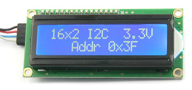
- I2C 16x2 Charcter Display
- DHT11 Sensor
Sketch
// Dragino Arduino (V 1.02) Shield Sketch with I2C LCD Display and DHT11 Sensor
// DL6WAB - www.dl6wab.de
// Based on Sketch Copyright (c) 2015 by Thomas Telkamp and Matthijs Kooijman
// https://github.com/matthijskooijman/arduino-lmic/blob/master/examples/ttn-abp/ttn-abp.ino
// https://github.com/matthijskooijman/arduino-lmic/blob/master/examples/ttn-otaa/ttn-otaa.ino// Libraries laden
#include <lmic.h> // MCCI LoRaWAN LMIC library
#include <hal/hal.h> // This the HAL to run LMIC on top of the Arduino environment
#include <SPI.h> // This library allows you to communicate with SPI devices, with the Arduino as the master device
#include <DHT.h> // DHT11 Sensor
#include <LiquidCrystal_I2C.h> // LCD via I2C Bus
//Sensor DHT11
#define DHTPIN 3 // Hier die Pin Nummer eintragen wo der Sensor angeschlossen ist
#define DHTTYPE DHT11 // Hier wird definiert was für ein Sensor (DHT11 oder DHT22) ausgelesen wird.
// LCD Display mit I2C Bus
LiquidCrystal_I2C
lcd1(0x26, 16, 2);
// LiquidCrystal_I2C // Zweites Display wenn erforderlich
// lcd2(0x27, 16, 2); // Zweites Display wenn erforderlich
// LoRaWAN NwkSKey (MSB), network session key
// This is the default Semtech key, which is used by the prototype TTN
// network initially.
static const PROGMEM u1_t NWKSKEY[16] = { 0x2B, 0x7E, 0x15, 0x16, 0x28, 0xAE, 0xD2, 0xA6, 0xAB, 0xF7, 0x15, 0x88, 0x09, 0xCF, 0x4F, 0x3C };
// LoRaWAN AppSKey (MSB), application session key
// This is the default Semtech key, which is used by the prototype TTN
// network initially.
static const u1_t PROGMEM APPSKEY[16] = { 0x2B, 0x7E, 0x15, 0x16, 0x28, 0xAE, 0xD2, 0xA6, 0xAB, 0xF7, 0x15, 0x88, 0x09, 0xCF, 0x4F, 0x3C };
// LoRaWAN DEVEUI (LSB)
static const u1_t PROGMEM DEVEUI[8] = { 0xXX, 0xXX, 0xXX, 0xXX, 0xXX, 0xD5, 0xB3, 0x70 };
// LoRaWAN end-device address (DevAddr)
static const u4_t DEVADDR = 0x260BXXXX; // Für jeden Node unterschiedlich anpassen!
// These callbacks are only used in over-the-air activation, so they are
// left empty here (we cannot leave them out completely unless
// DISABLE_JOIN is set in config.h, otherwise the linker will complain).
void os_getArtEui (u1_t* buf) { }
void os_getDevEui (u1_t* buf) { }
void os_getDevKey (u1_t* buf) { }
// Schedule TX every 60 seconds (might become longer due to duty
// cycle limitations).
const unsigned TX_INTERVAL = 60;
// Pin mapping Dragino Arduino Shield
const lmic_pinmap lmic_pins = {
.nss = 10,
.rxtx = LMIC_UNUSED_PIN,
.rst = 9,
.dio = {2, 6, 7},
};
// init. DHT
DHT dht(DHTPIN, DHTTYPE);
// payload to send to TTN gateway
static uint8_t payload[5];
static osjob_t sendjob;
// Events
void onEvent (ev_t ev) {
// Hier definieren wir die Verweilzeit die gewartet wird
// bis der Sensor wieder ausgelesen wird. Da der DHT11
// auch ca. 2 Sekunden braucht um seine Werte zu aktualisieren
// macht es keinen Sinn, ihn schneller auszulesen!
delay(2000);
// Sensor auslesen und in Variablen speichern
float humid = dht.readHumidity(); // Lesen der Luftfeuchtigkeit und speichern in die Variable humid
float temp = dht.readTemperature(); // Lesen der Temperatur in °C und speichern in die Variable temp
// Serielle Ausgabe
Serial.println("------------------------------------------------------------------");
Serial.print("Luftfeuchtigkeit: ");
Serial.print(humid); // Ausgeben der Luftfeuchtigkeit
Serial.print(" %\t"); // Tabulator
Serial.print("Temperatur: ");
Serial.print(temp); // Ausgeben der Temperatur
Serial.println(" C");
// LCD Ausgabe
lcd1.clear();
lcd1.setCursor(0, 0);
lcd1.print("LuFeu = ");
lcd1.print(humid);
lcd1.setCursor(0, 1);
lcd1.print("Temp = ");
lcd1.print(temp);
delay(2000);
//Serielle Ausgabe
Serial.print("opmode ");
Serial.println(LMIC.opmode);
Serial.print(LMIC.freq);
Serial.println(" Hz ");
// LCD Ausgabe
lcd1.clear();
lcd1.setCursor(0, 0);
lcd1.print("OpMo = ");
lcd1.print(LMIC.opmode);
lcd1.setCursor(0, 1);
lcd1.print("Freq = ");
lcd1.print(LMIC.freq);
delay(2000);
// Events
switch (ev) {
case EV_SCAN_TIMEOUT:
Serial.println(F("EV_SCAN_TIMEOUT"));
break;
case EV_BEACON_FOUND:
Serial.println(F("EV_BEACON_FOUND"));
break;
case EV_BEACON_MISSED:
Serial.println(F("EV_BEACON_MISSED"));
break;
case EV_BEACON_TRACKED:
Serial.println(F("EV_BEACON_TRACKED"));
break;
case EV_JOINING:
Serial.println(F("EV_JOINING"));
break;
case EV_JOINED:
Serial.println(F("EV_JOINED"));
break;
case EV_RFU1:
Serial.println(F("EV_RFU1"));
break;
case EV_JOIN_FAILED:
Serial.println(F("EV_JOIN_FAILED"));
break;
case EV_REJOIN_FAILED:
Serial.println(F("EV_REJOIN_FAILED"));
break;
break;
case EV_TXCOMPLETE:
Serial.println(F("EV_TXCOMPLETE: "));
if (LMIC.txrxFlags & TXRX_ACK) {
//rxcounter++;
Serial.println(F("Received ack."));
}
if (LMIC.dataLen) {
Serial.println(F("received "));
Serial.print(LMIC.dataLen);
Serial.print(F(" bytes of payload : "));
for (int d = 0; d < LMIC.dataLen; d++) {
Serial.print(*(uint8_t *)(LMIC.frame + LMIC.dataBeg + d), HEX);
Serial.print(" ");
}
// rxcounter2 += LMIC.dataLen;
}
// Schedule next transmission
Serial.print(F("tx channel "));
Serial.print(LMIC.txChnl);
Serial.print(F(", data rate "));
Serial.println(LMIC.datarate);
// LCD Ausgabe
lcd1.clear();
lcd1.setCursor(0, 0);
lcd1.print("TX Channel = ");
lcd1.print(LMIC.txChnl);
lcd1.setCursor(0, 1);
lcd1.print("Data Rate = ");
lcd1.print(LMIC.datarate);
delay(2000);
// Events
os_setTimedCallback(&sendjob, os_getTime() + sec2osticks(TX_INTERVAL), do_send);
break;
case EV_LOST_TSYNC:
Serial.println(F("EV_LOST_TSYNC"));
break;
case EV_RESET:
Serial.println(F("EV_RESET"));
break;
case EV_RXCOMPLETE:
// data received in ping slot
Serial.println(F("EV_RXCOMPLETE"));
break;
case EV_LINK_DEAD:
Serial.println(F("EV_LINK_DEAD"));
break;
case EV_LINK_ALIVE:
Serial.println(F("EV_LINK_ALIVE"));
break;
default:
Serial.println(F("Unknown event"));
break;
}
}
// Payload Senden
void do_send(osjob_t* j) {
// Check if there is not a current TX/RX job running
if (LMIC.opmode & OP_TXRXPEND) {
Serial.println(F("OP_TXRXPEND, not sending"));
} else {
// read the temperature from the DHT11
float temperature = dht.readTemperature();
Serial.print("Temp = "); Serial.print(temperature);
Serial.print(" C, ");
// adjust for the f2sflt16 range (-1 to 1)
temperature = temperature / 100;
// read the humidity from the DHT11
float rHumidity = dht.readHumidity();
Serial.print("RH = ");
Serial.print(rHumidity);
Serial.println(" %");
// adjust for the f2sflt16 range (-1 to 1)
rHumidity = rHumidity / 100;
// float -> int
// note: this uses the sflt16 datum (https://github.com/mcci-catena/arduino-lmic#sflt16)
uint16_t payloadTemp = LMIC_f2sflt16(temperature);
// int -> bytes
byte tempLow = lowByte(payloadTemp);
byte tempHigh = highByte(payloadTemp);
// place the bytes into the payload
payload[0] = tempLow;
payload[1] = tempHigh;
// float -> int
uint16_t payloadHumid = LMIC_f2sflt16(rHumidity);
// int -> bytes
byte humidLow = lowByte(payloadHumid);
byte humidHigh = highByte(payloadHumid);
payload[2] = humidLow;
payload[3] = humidHigh;
// prepare upstream data transmission at the next possible time.
// transmit on port 1 (the first parameter); you can use any value from 1 to 223 (others are reserved).
// don't request an ack (the last parameter, if not zero, requests an ack from the network).
// Remember, acks consume a lot of network resources; don't ask for an ack unless you really need it.
LMIC_setTxData2(1, payload, sizeof(payload) - 1, 0);
}
// Next TX is scheduled after TX_COMPLETE event.
}
void setup() {
Serial.begin(115200);
Serial.println(F("starting"));
dht.begin();
lcd1.begin(16, 2);
// lcd2.begin(16,2);
lcd1.init();
// lcd2.init();
lcd1.backlight();
// lcd2.backlight();
lcd1.setCursor(0, 0);
// lcd2.setCursor(0, 1);
// LMIC init
os_init();
// Reset the MAC state. Session and pending data transfers will be discarded.
LMIC_reset();
// Set static session parameters. Instead of dynamically establishing a session
// by joining the network, precomputed session parameters are be provided.
#ifdef PROGMEM
// On AVR, these values are stored in flash and only copied to RAM
// once. Copy them to a temporary buffer here, LMIC_setSession will
// copy them into a buffer of its own again.
uint8_t appskey[sizeof(APPSKEY)];
uint8_t nwkskey[sizeof(NWKSKEY)];
memcpy_P(appskey, APPSKEY, sizeof(APPSKEY));
memcpy_P(nwkskey, NWKSKEY, sizeof(NWKSKEY));
LMIC_setSession (0x1, DEVADDR, nwkskey, appskey);
#else
// If not running an AVR with PROGMEM, just use the arrays directly
LMIC_setSession (0x1, DEVADDR, NWKSKEY, APPSKEY);
#endif
// Set up the channels used by the Things Network, which corresponds
// to the defaults of most gateways. Without this, only three base
// channels from the LoRaWAN specification are used, which certainly
// works, so it is good for debugging, but can overload those
// frequencies, so be sure to configure the full frequency range of
// your network here (unless your network autoconfigures them).
// Setting up channels should happen after LMIC_setSession, as that
// configures the minimal channel set.
LMIC_setupChannel(0, 868100000, DR_RANGE_MAP(DR_SF12, DR_SF7), BAND_CENTI); // g-band
LMIC_setupChannel(1, 868300000, DR_RANGE_MAP(DR_SF12, DR_SF7B), BAND_CENTI); // g-band
LMIC_setupChannel(2, 868500000, DR_RANGE_MAP(DR_SF12, DR_SF7), BAND_CENTI); // g-band
LMIC_setupChannel(3, 867100000, DR_RANGE_MAP(DR_SF12, DR_SF7), BAND_CENTI); // g-band
LMIC_setupChannel(4, 867300000, DR_RANGE_MAP(DR_SF12, DR_SF7), BAND_CENTI); // g-band
LMIC_setupChannel(5, 867500000, DR_RANGE_MAP(DR_SF12, DR_SF7), BAND_CENTI); // g-band
LMIC_setupChannel(6, 867700000, DR_RANGE_MAP(DR_SF12, DR_SF7), BAND_CENTI); // g-band
LMIC_setupChannel(7, 867900000, DR_RANGE_MAP(DR_SF12, DR_SF7), BAND_CENTI); // g-band
LMIC_setupChannel(8, 868800000, DR_RANGE_MAP(DR_FSK, DR_FSK), BAND_MILLI); // g2-band
// TTN defines an additional channel at 869.525Mhz using SF9 for class B
// devices' ping slots. LMIC does not have an easy way to define set this
// frequency and support for class B is spotty and untested, so this
// frequency is not configured here.
// Disable link check validation
LMIC_setLinkCheckMode(0);
// Set data rate and transmit power (note: txpow seems to be ignored by the library)
LMIC_setDrTxpow(DR_SF7, 14);
// Start Send Job
do_send(&sendjob);
}
void loop() {
os_runloop_once();
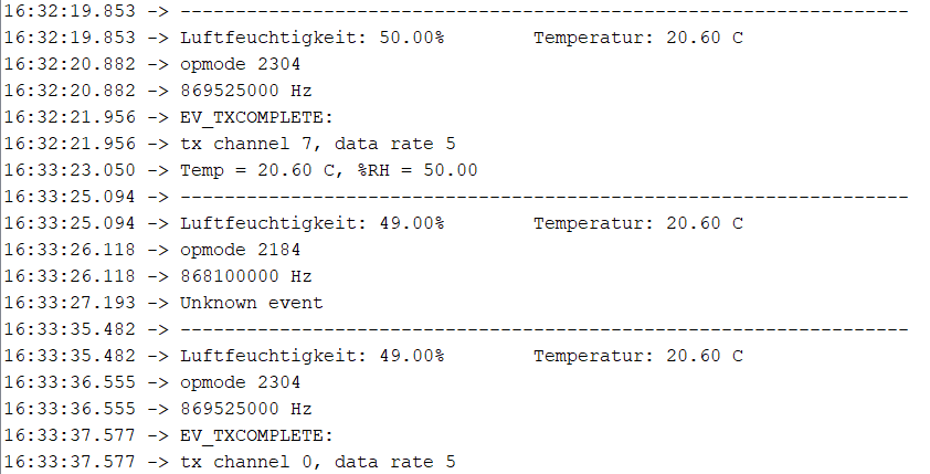
}Payload (serielle Ausgabe)
Payload Formatter
function Decoder(bytes, port) {
var decoded = {};
rawTemp = bytes[0] + bytes[1] * 256;
decoded.degreesC = sflt162f(rawTemp) * 100;
rawHumid = bytes[2] + bytes[3] * 256;
decoded.humidity = sflt162f(rawHumid) * 100;
return decoded;
}
function sflt162f(rawSflt16)
{
// rawSflt16 is the 2-byte number decoded from wherever;
// it's in range 0..0xFFFF
// bit 15 is the sign bit
// bits 14..11 are the exponent
// bits 10..0 are the the mantissa. Unlike IEEE format,
// the msb is transmitted; this means that numbers
// might not be normalized, but makes coding for
// underflow easier.
// As with IEEE format, negative zero is possible, so
// we special-case that in hopes that JavaScript will
// also cooperate.
//
// The result is a number in the open interval (-1.0, 1.0);
//
// throw away high bits for repeatability.
rawSflt16 &= 0xFFFF;
// special case minus zero:
if (rawSflt16 == 0x8000)
return -0.0;
// extract the sign.
var sSign = ((rawSflt16 & 0x8000) != 0) ? -1 : 1;
// extract the exponent
var exp1 = (rawSflt16 >> 11) & 0xF;
// extract the "mantissa" (the fractional part)
var mant1 = (rawSflt16 & 0x7FF) / 2048.0;
// convert back to a floating point number. We hope
// that Math.pow(2, k) is handled efficiently by
// the JS interpreter! If this is time critical code,
// you can replace by a suitable shift and divide.
var f_unscaled = sSign * mant1 * Math.pow(2, exp1 - 15);
return f_unscaled;
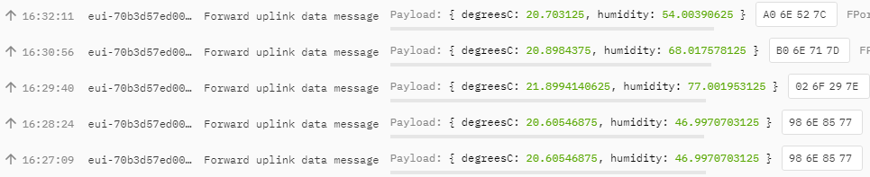
}Ergebnis im TTN